
EMG (Electromyography) is a test that analyzes the electrical impulses generated by the contraction of muscle fibers.
This allows us to control any object with the simple movement of a hand. The potential is limitless: it can be applied to hardware (like a servo motor, an RC car, or a robotic arm) or even software (such as controlling a character in a video game).
In this project, we will see how to move a servo motor every time we open and close our hand.
To see the project in action and follow the steps visually, check out the full video tutorial on my channel:
To replicate this project you will need:
- Arduino (e.g., Uno, Nano, etc.)
- EMG Sensor Kit (in this guide, the Fyearfly kit was used)
- Cable with its electrodes
- Servo motor
- 2x 9V Batteries
- 3x Battery connectors
- Jumper Wires
- Breadboard
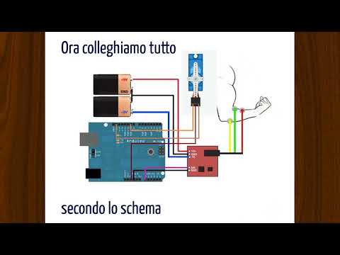
The connections must be made according to the following schematic:
- +Vs: Connected to the
+of the batteries. - -Vs: Connected to the
-of the batteries. - GND (first): Connected to the
GNDof the batteries. - SIG: Connected to the
A0analog pin on Arduino. - GND (second): Connected to the
GNDof Arduino.
- Orange Wire (Signal): Connected to digital pin
9. - Red Wire (Power): Connected to
+5Von Arduino. - Brown Wire (Ground): Connected to
GNDon Arduino.
In this case, we are going to apply the electrodes to the arm, specifically on a muscle called the flexor carpi radialis. To get a proper reading of the electrical impulses, follow this color-coding scheme:
- 🔴 Red: Must be applied to the end of the muscle.
- 🟢 Green: Must be applied to the beginning of the muscle.
- 🟡 Yellow: Must be applied to a bony part of the arm (this acts as a reference/ground to isolate noise).
The raw signal coming from an EMG sensor tends to be very noisy and "spiky". If we used this data directly to move the servo, we would get a jerky movement.
To solve this problem, the code implements a Moving Average algorithm:
- Sampling: Arduino continuously collects a defined number of readings (
DIM) into an array. - Smoothing: It calculates the average of these values, returning a smooth and linear curve visible on the Arduino IDE's Serial Plotter.
- Actuation: If the calculated average exceeds the contraction threshold (
SOGLIA), the servo moves to 170°. Otherwise, it stays at rest at 10°.
Every person and every electrode placement generates signals of different intensities. For the project to work properly, it is crucial to calibrate two constants at the beginning of the code:
// Adjusts the smoothness of the movement
#define DIM 50

// Adjusts the sensitivity to muscle contraction
#define SOGLIA 100
-
DIM(Array Size): Indicates how many samples to use to calculate the average.-
The larger it is: the movement is more linear but slightly delayed.
-
The smaller it is: the response is reactive, but the movement could be jerky.
-
-
SOGLIA(Contraction Trigger): It is the value beyond which Arduino considers the muscle "contracted".-
If the servo moves by itself at rest, increase the threshold.
-
If you have to strain too much to move the servo, decrease the threshold.
-